

Table of Contents
Transmission media, in simple terms, refers to the physical path that conveys information from a source to its destination. This medium can encompass free space, metallic cables, or fiber-optic cables, facilitating the transmission of data through electromagnetic signals.
Categories of Transmission Media:
In the realm of data communication, transmission media falls into two main categories:
- Guided Media
- Unguided Media
Transmission media can be broadly categorized into guided and unguided types. Guided media, exemplified by twisted-pair cables, coaxial cables, and fiber-optic cables, establishes a defined path for data transmission. This type is suitable for point-to-point or multipoint communication, where considerations like the medium and cable length play a vital role.

|
|
Categories of Transmission Media
|
On the flip side, unguided media operates in free space, allowing data transmission without a specific physical pathway. In this mode, electromagnetic signals are employed for communication, with careful attention to managing potential noise interference.
1. Guided Media
Guided media establishes a physical connection, serving as a conduit between devices. When a signal travels through these media, it is directed and confined by the physical medium itself. Examples of guided media include twisted-pair and coaxial cables, utilizing metallic conductors to carry signals as electric currents. Optical fiber cables are also guided media, accepting and transporting signals in the form of light.
Twisted Pair Cable:
A twisted pair cable consists of two conductors, typically made of copper, each individually insulated and then wound together, as depicted in the below Figure.

|
| Twisted Pair Cable |
One of these wires serves to transmit signals to the receiver, while the other functions solely as a ground reference. The receiver utilizes the difference between these two wires. However, when the sender transmits a signal on one wire, interference (noise) and crosstalk may impact both wires, introducing unwanted signals.
To mitigate the impact of undesirable signals, the wires are twisted. If the wires run parallel, the effects of noise or crosstalk aren't the same on both wires due to their different locations relative to the sources (e.g., one closer and the other farther). Twisting the pair helps maintain balance.
The data rate supported over a twisted pair is inversely proportional to the square of the line length. A maximum transmission distance of 1 km can be achieved for data rates up to 1 Mb/s. For analog voice signals, amplifiers are required approximately every 6 km, and for digital signals, repeaters are needed every 2 km.
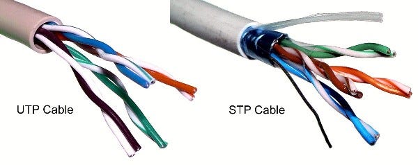
Unshielded vs. Shielded Twisted-Pair Cable:
The prevalent type of twisted pair cable extensively used in communications is known as Unshielded Twisted Pair (UTP) . Additionally, IBM has introduced Shielded Twisted Pair (STP) for specific applications. STP cable incorporates a metal shield or braided mesh covering that envelops each pair of insulated conductors. While the metal shielding enhances cable quality by preventing noise or crosstalk interference, it adds bulk and increases cost. The figure illustrates the distinction between UTP and STP.
|
|
Unshielded and Shielded Twisted-Pair cable
|
Categories of Unshielded Twisted Pair (UTP) Cable:
The Electronic Industries Association (EIA) has established standards categorizing Unshielded Twisted-Pair (UTP) cables into seven categories, each tailored for specific purposes.
- CAT1: Primarily used for telephone wires, particularly by telecommunication companies offering ISDN and PSTN services.
- CAT2: Employed mostly in token ring networks, supporting speeds up to 4 Mbps. While almost obsolete, it meets the requirements for the almost extinct 10 Mbps speed.
- CAT3, CAT4, CAT5/5e, CAT6 & CAT7: Geared towards network wire specifications, capable of supporting computer network and telephone traffic. CAT5e, the most popular, replaced old coaxial cables due to the growing demand for faster and more reliable networks.
- CAT3 and CAT4: Utilized in Token Ring networks, where CAT3 supports a maximum of 10 Mbps, while CAT4 extends the limit to 16 Mbps. Both categories have a maximum range of 100 meters.
- CAT5e: Improved version of CAT5, featuring enhanced crosstalk specifications, supporting speeds of up to 1 Gbps. It is the widely used cabling specification globally.
- CAT6: Initially designed to support gigabit Ethernet, it is similar to CAT5e but includes a physical separator between pairs to reduce electromagnetic interference. CAT6 can handle speeds of 1 Gbps for lengths up to 100 meters, and 10 Gbps for up to 55 meters.
- CAT7: A newer specification designed for speeds of 10 Gbps at lengths up to 100 meters. It features four individually shielded pairs along with an additional cable shield to protect signals from crosstalk and electromagnetic interference.
Understanding Unshielded Twisted-Pair Connectors (RJ45):
The prevalent Unshielded Twisted-Pair (UTP) connector, widely known as RJ45, holds significance in networking and is an abbreviation for "registered jack." In an Ethernet cable, eight color-coded wires are intricately twisted into four pairs, each adhering to a common color theme. The RJ45 connector utilizes an 8P8C modular connector, denoting 8 Positions and 8 Contacts. This keyed connector ensures a single insertion orientation.

|
| RJ 45 Connector |
Characteristics of Twisted Pair Cable:
- Requires amplifiers every 5-6 km for analog signals.
- Demands repeaters every 2-3 km for digital signals.
- Attenuation strongly depends on frequency.
- Susceptible to interference and noise.
Applications:
- Used in telephone lines, providing voice and data channels.
- The local loop, linking subscribers to central telephone offices, commonly employs UTP cables.
- DSL lines also utilize UTP cables.
- UTP cables are prevalent in LANs such as 10Base-T and 100Base-T.
Advantages and Disadvantages
Advantages:
- Inexpensive, widely available, and lightweight.
- Flexible and easy to install.
Disadvantages:
- Vulnerable to interference and noise.
- Analog signals require repeaters every 5-6 km.
- Digital signals necessitate repeaters every 2-3 km.
- Relatively low bandwidth (3000Hz).
Coaxial Cable:
A coaxial cable, often referred to as "coax," consists of two conductors, allowing it to operate across a broader range of frequencies. It features a hollow outer cylindrical conductor that surrounds a single inner wire conductor. The inner conductor is held in place by regularly spaced insulating rings or a solid dielectric material. The outer conductor is protected with a shield or coat.

A single coaxial cable typically has a diameter ranging from 1 to 2.5 cm. Its design enables it to be used over longer distances and supports a larger number of channels on a common line compared to twisted pair cables. Coaxial cables find applications in both baseband and broadband communications.
In baseband Local Area Networks (LANs) , data rates fall within the range of 1 KHz to 20 MHz, covering distances up to 1 Km. For broadband applications, these cables offer data rates ranging from 300 to 400 MHz. The versatility of coaxial cables makes them suitable for various communication scenarios, ensuring reliable transmission over extended distances.
In this unit, our emphasis shifts to the exploration of specific guided media, including coaxial cable, twisted pair, and fiber optic cable. These media play essential roles in various communication scenarios.
Standards
Coaxial cables are categorized based on their Radio Government (RG) ratings. Each RG number signifies a specific set of physical characteristics, including the inner conductor's wire size, the thickness and type of the inner insulator, the shield's construction, and the size and type of the outer casing. Each cable, defined by an RG rating, is tailored for a specific purpose.
|
Category |
Impedance |
Use |
|
RG-59 |
75Ω |
Cable Television |
|
RG-58 |
50Ω |
Thin Ethernet |
|
RG-11 |
50Ω |
Thick Ethernet |
Understanding Coaxial Cable Connectors:
For connecting coaxial cables to various devices, coaxial connectors play a crucial role. The widely utilized type of connector today is the Bayone-Neil-Concelman, abbreviated as the BNC connector. There are three key types of connectors:
1. BNC Connector:
- Purpose: Links the cable's end to a device, like a TV set.
2. BNC T Connector:
- Application: Employed in Ethernet networks to extend connections to computers or other devices.
3. BNC Terminator:
- Function: Positioned at the cable's end to prevent signal reflection.
These connectors serve distinct purposes in establishing and optimizing connections in coaxial cable setups.

|
|
Coaxial Cable Connector
|
Applications
The coaxial cable serves as a versatile transmission medium employed in various applications, including:
- Television distribution
- Long-distance telephone transmission
- Short-run computer system links
- Local area networks
Coaxial cable was extensively used in analog telephone systems, capable of carrying 10,000 voice signals. In digital telephone systems, it conveyed digital data at speeds up to 600 Mbps. However, fiber optic cables have largely replaced coaxial cables in telephone systems today. Cable TV networks initially used coaxial cables extensively, but fiber-optic cables have progressively taken over, with coaxial cables remaining at network boundaries near customer premises. Digital TV commonly employs RG-59 coaxial cable.
Advantages & Disadvantages
Advantages:
- Greater channel capacity than twisted pair.
- Greater bandwidth compared to twisted pair.
- Lower error rate (Approx. 10^-9 bps)
Disadvantages:
- Installation can be challenging.
- Higher installation costs.
- Susceptible to noise interference.
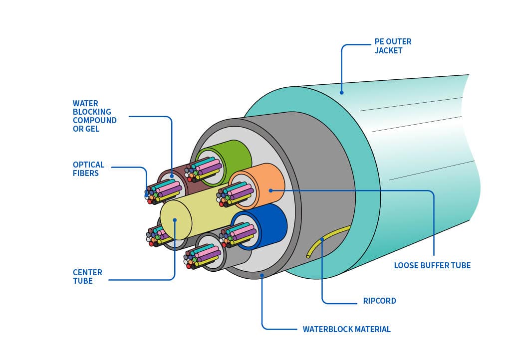
Fiber Optic Cable:
Instead of relying on electric signals, fiber optic cables utilize light to transmit data, functioning on the principle of total internal reflection. Composed of glass fibers finer than a human hair, these cables guide light beams across extensive distances. An optical fiber comprises a slender glass core enveloped by a cladding layer, with some fibers being made of plastic, which, though easier to install, has limited light transmission compared to glass.
|
|
Fiber optic Cable
|
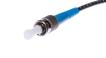
Types of Fiber-Optic Cable Connectors:
-
Subscriber Channel Connector: Primarily employed in cable TV, featuring a push/pull locking system.
- Straight-Tip Connector: Connects cable to networking devices, employing a bayonet locking system, known for reliability.
- MT–RJ Connector: Comparable in size to RJ45, providing versatility in applications.
|
| Fiber Optic cable connector |
Applications:
- Commonly used as backbone networks (e.g., SONET) due to cost-effective wide bandwidth.
- Hybrid networks, combining optical fiber and coaxial cable, are often employed by some cable TV companies.
- In LANs such as 100Base-FX network (Fast Ethernet) and 1000Base-X.
Advantages and Disadvantages
Advantages:
- High bandwidth capacity (multiple gigabits per second).
- Extended distances between devices (ranging from 2 to over 60 kilometers).
- Immunity to electromagnetic interferences.
- Simultaneous transmission and reception of very high frequencies.
- Less signal attenuation, lightweight, and enhanced tapping immunity.
Disadvantages:
- Installation and maintenance can be challenging.
- Unidirectional light propagation and associated costs.
Choosing Fiber-Optic Cable:
- Opt for fiber-optic cable for high-speed, secure data transmission over long distances.
- Avoid it if on a tight budget without the expertise for proper installation and device connection.
|
Characteristic |
Twisted Pair Cable |
Coaxial Cable |
Optical Fiber |
|
Signal Transmission Medium |
Electrical form over metallic
conducting wires |
Inner conductor of the cable |
Optical form over a glass fiber |
|
Noise Immunity |
Low, leading to more distortion |
Higher due to the presence of
shielding conductor |
Higher, unaffected by
electrical noise |
|
Effect of External Magnetic
Field |
Affected |
Less affected |
Not affected |
|
Short Circuit Possibility |
Possible |
Possible |
Not Possible |
|
Cost |
Cheapest |
Moderately expensive |
Expensive |
|
Data Rate Support |
Low |
Moderately High |
Very High |
|
Bandwidth |
Low |
Moderately High |
Very High |
|
Installation |
Easy |
Fairly easy |
Difficult |
This table provides a comparison between Twisted Pair Cable, Coaxial Cable, and Optical Fiber based on various characteristics, including signal transmission, noise immunity, susceptibility to external factors, short circuit possibility, cost, data rate support, bandwidth, and ease of installation.
2. Unguided (Wireless) Medium:
Unguided media, commonly known as wireless communication, enables data transmission without relying on a physical conductor. Wireless electromagnetic signals serve as the means for sending data.
Types of Wave Propagation:
Before delving into wireless transmission media types, it's crucial to understand how wireless signals travel. These signals can propagate through three distinct methods:
i. Ground-wave Propagation:
- Follows the contour of the earth.
- Propagates considerable distances.
- Frequencies up to 2 MHz.
- Example: AM radio.

|
|
Ground-wave propagation
|
ii. Sky-wave Propagation:
- The signal is reflected from the ionized layer of the atmosphere back down to Earth.
- Can travel multiple hops between the ionosphere and the earth's surface.
- Reflection effect caused by refraction.
- Examples: Amateur radio, CB radio.

|
|
Sky-wave propagation
|
iii. Line-of-sight Propagation:
Transmitting and receiving antennas must be within the line of sight.- Satellite communication – signal above 30 MHz not reflected by the ionosphere.
- G round communication – antennas within effective line of sight due to refraction.

|
|
Line-of-sight propagation
|
Types of Unguided (Wireless) Medium:
There are three main types of unguided media:

|
|
Categories of the wireless medium
|
1. Radio Waves:
- Frequency range: 3 KHz to 1 GHz.
- Omni-directional propagation.
- Suitable for long-distance broadcasting.
- Can penetrate walls at low and medium frequencies.
2. Microwaves:
- Frequency range: 1 to 300 GHz.
- Unidirectional propagation.
- Requires alignment of transmitting and receiving antennas.
- Line-of-sight propagation; is effective for focused communication.
3. Infrared:
- Frequency range: 300 GHz to 400 GHz.
- Used for short-range communication.
- High-frequency signals that cannot penetrate walls.
- Prevents interference between different systems.
- Ideal for transmitting digital data at high speeds.
Choice of Transmission Media:
The selection of a transmission medium is critical, impacting network cost, operating speed, and error rates. A transmission medium should be durable, reliable, cost-effective, immune to noise, and easy to install, maintain, and reconfigure.
Comparison between Guided and Unguided Media
Guided media and unguided media differ from each other in the following ways.
|
GuidedMedia |
Unguided Media |
|
The signal energy is contained and guided within a solid medium |
The signal energy propagates in the form of unguided electromagnetic waves. |
|
Examples of wired media are twisted-pair wires, coaxial cables, and optical fiber cables. |
Microwaves, radio waves, and infrared lights are examples of wireless media. |
|
Used for point-to-point communication |
Used for radio broadcasting in all directions |
|
Wired media leads to discrete network topology |
Wireless media leads to continuous network topology |
|
Additional transmission capacity can be procured by adding more wire |
It is not possible to procure additional capacity. |
|
Installation is costly and time-consuming |
Installation needs less time and money |
|
Attenuation depends exponentially on the distance. |
Attenuation is proportional to the square of the distance. |


